I basically made Arthur, my delta robot, so that I could play with the fascinatingly complex inverse kinematics equations required to get a delta robot running. In the same way that kinematic equations predict the result of a system, an inverse kinematic equation determines the system based on a desired result. In this case, the desired result is always a coordinate in 3D space, and the system is our delta robot with its lever arms at 3 different angles. The inverse kinematic equation takes in the coordinates and gives us the angles of the arms to reach those coordinates.
Delta Robot aka Arthur moves from Noah Todd on Vimeo.
If you’re interested in understanding how this works, let’s dive in!
I separated the movement of the delta robot into 3 functions. The first, setLevers() is a simple function that sets the levers (the yellow pieces) to given angles. I’m going to skip over this because it is robot specific and basic.
void setLevers(float f, float l, float r){ //f is front, l is left, r is right
 if (f > 150 || l > 150 || r > 150 || f < 15 || l < 15 || r < 15){
 Serial.println("inputs are out of range for lever arms");
 return; // this checks for invalid inputs
 }
 // TODO: create another indicator that the inputs are invalid
 int fcor = 275; int rcor = 350; int lcor = 375; //fcor = front correction
 long upperLimit = 800; // upper limit ~= 800 = 125 degrees to straight down (((1900)))
 long lowerLimit = 2300;// lower limit ~= 2300 = 35 degrees to straight down (((925 )))
 myservofront.writeMicroseconds((f - 35)*(upperLimit - lowerLimit)/(125-35) + fcor + lowerLimit); // tell servo to go to position in variable 'pos'
 myservoright.writeMicroseconds((r - 35)*(upperLimit - lowerLimit)/(125-35) + rcor + lowerLimit);
 myservoleft.writeMicroseconds((l - 35)*(upperLimit - lowerLimit)/(125-35) + lcor + lowerLimit);
}
The second function, leverCalc(), is mathematically intense, and this is where the angles of the levers are determined. It takes the coordinates of the desired position (x, y, z) and returns an angle for the lever.
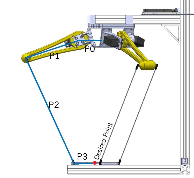
The function starts by defining the lengths of the different linkages (P0,P1,P2,P3, as shown in the picture above) along with some variables.
I did the mathematical calculation for this by simplifying the structure into a 2D system for each arm of the delta. To do this, I also had to account for the lateral movement of the linkage of each arm. To adjust the length of P2 when it is projected onto my 2D plane, I created a new variable mP2 or modified P2. I set this equal to the project length by using pythagorean’s theorem (line 3).
Next, I eliminated P0 and P3 by subtracting and adding them respectively to y. Keep in mind that my 2D plane is the y,z plane, not the x,y plane. Using the new y, I found the hypotenuse (h) of y and z, which is also the length of the third side in the triangle created by segments P1 and mP2.
Finally, I used the law of cosines to find the angle between the hypotenuse and P1. I added that to the arccos of z over the hypotenuse to get theta in radians. At the end, I converted theta to degrees.
float leverCalc(float x, float y, float z){
 float p0 = 75, p1 = 150, p2 = 315, p3 = 50, mp2, h, theta; // refer to picture < picture of linkages > for explanations of names. all units in mm
 mp2 = sqrt( pow(p2,2) - pow(x,2) ); // adjusts the linkage length to compensate for the tilt of the linkages
 y = y + p3 - p0; // p0 is the distance from the base of the lever arm to the center of the lever arms
 // p3 is the distance from the center of the tooltip to the bottom ends of the linkages
 // This whole adjustment makes y (the change in y) the y distance from the base of the levers to the ends of the linkages
 h = sqrt( pow(y,2) + pow(z,2) ); // calculates h. Refer to < picture of linkages >
 theta = atan( y / z ) + acos( ( pow(h,2) + pow(p1,2) - pow(mp2,2) ) / (2*h*p1) );
 theta = theta / PI * 180; // adjust theta to match setLever() parameters
 return theta;
 }
The final function, moveTo, just calls the leverCalc function 3 times and adjusts the coordinates for each lever. Then, it does a quick check to make sure the values are in range. Finally, it sets the levers to the desired coordinates.
void moveTo(float x, float y, float z){
 float front, right, left, p2 = 315; // these are the variables for the lever angles
 front = leverCalc(x, y, z); //calculates lever angle for the front lever
 float ry = -y*sin(PI/6) + x*cos(PI/6); // adjust x, y, and z values for the left lever
 float rx = -y*cos(PI/6) - x*sin(PI/6);
 right = leverCalc(rx, ry, z); //calculates lever angle for the left lever
 float ly = -y*sin(PI/6) - x*cos(PI/6); // adjust x, y, and z values for the right lever
 float lx = y*cos(PI/6) - x*sin(PI/6);
 left = leverCalc(lx, ly, z); //calculates lever angle for the right lever
 // Throws error and prevents movement if the input is out of bounds of the mechanism
 if ( atan(x/p2) > PI/6 || atan(rx/p2) > PI/6 || atan(lx/p2) > PI/6 ){
 Serial.println("out of bounds");
 return;
 }
 setLevers(front, left, right); // sets levers to desired angles
 cx = x; cy = y; cz = z;
 }
The moveTo() function is rather basic, and I made a lineTo function (which is flaunted in the above video) that is much smoother. More on that in a later blog post.
